Choose a crystal or oscillator by matching the receiving IC's clock requirements first. A passive crystal needs a compatible oscillator circuit; a powered oscillator supplies a clock output. Then compare frequency accuracy, loading, startup, drive limits, and package details before requesting parts.
This crystal oscillator selection guide helps hardware and procurement teams turn those checks into a purchasing specification. The passive-crystal and active-oscillator checks are separated so each sourcing request carries the correct electrical requirements.
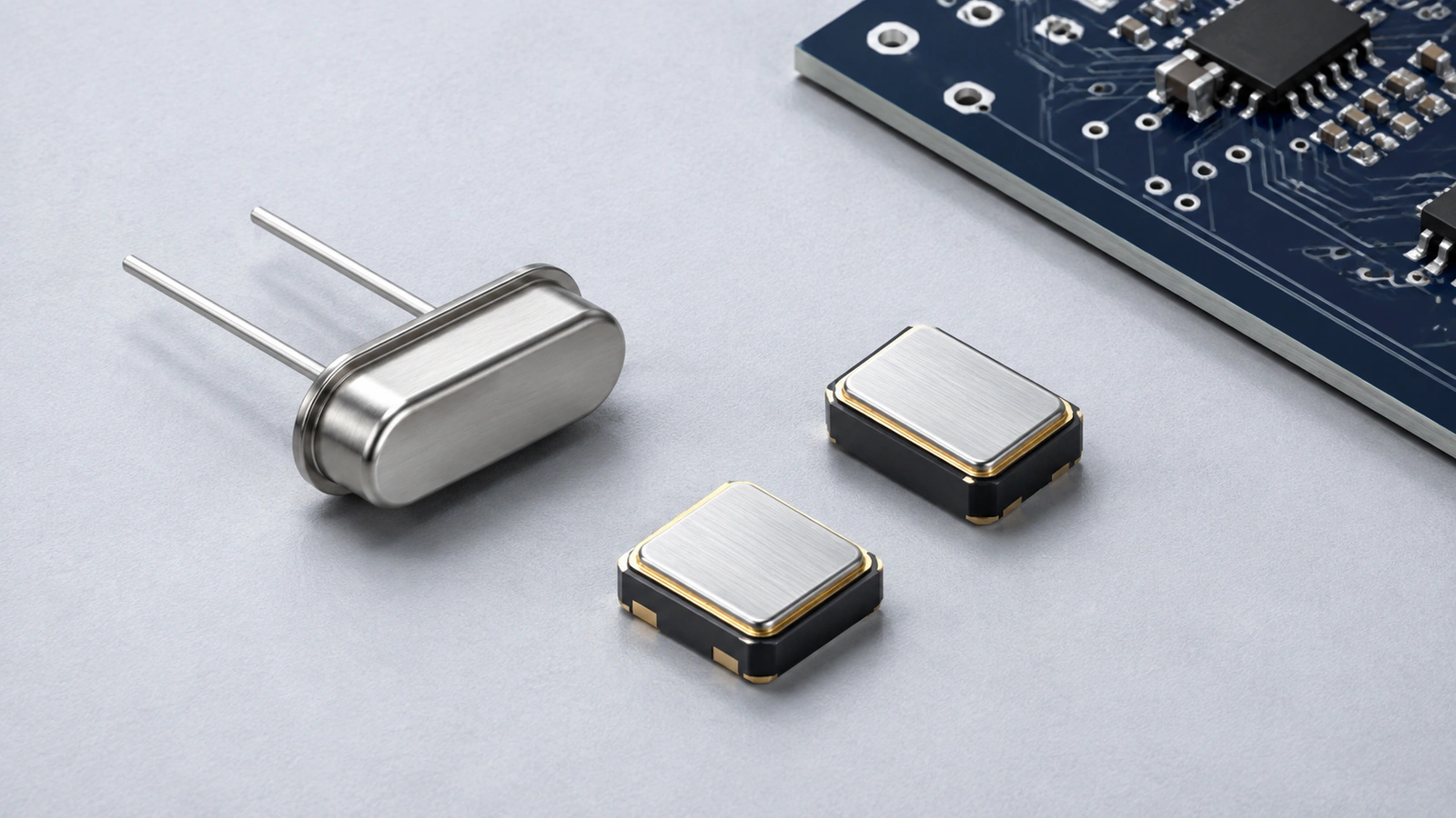 Conceptual timing-component illustration; package appearance does not establish electrical compatibility.
How to choose a crystal oscillator
Use the receiving IC datasheet, its hardware design guidance, and the timing-component datasheet together:
Identify the clock source: a passive crystal connected to an oscillator circuit, or a powered oscillator connected to a clock input.
Confirm the frequency, operating mode, and total permitted frequency error under the required conditions.
For a crystal, compare load capacitance, maximum equivalent series resistance (ESR), shunt capacitance where specified, and drive limits with the circuit.
For an active oscillator, compare supply voltage, signaling format, output load, startup behavior, and jitter requirements.
Check the mechanical drawing, pad functions, temperature grade, and assembly requirements.
Record the board validation and engineering approval needed before purchasing an alternate.
A BOM line that says only “16 MHz crystal” leaves several of these decisions open. Keep the full ordering code when a part is already approved. If the design is still being evaluated, label the request as candidate sourcing and attach its electrical requirements. For a multi-line request, use the BOM preparation checklist to keep full ordering codes, quantities, and alternate restrictions clear.
Crystal vs. oscillator: start with the circuit
A quartz crystal unit is a passive resonator. It works with a sustaining circuit, often inside a microcontroller or clock IC. A packaged crystal oscillator contains that circuit and provides a powered clock output. Epson's explanation of crystal units and oscillators describes the distinction.
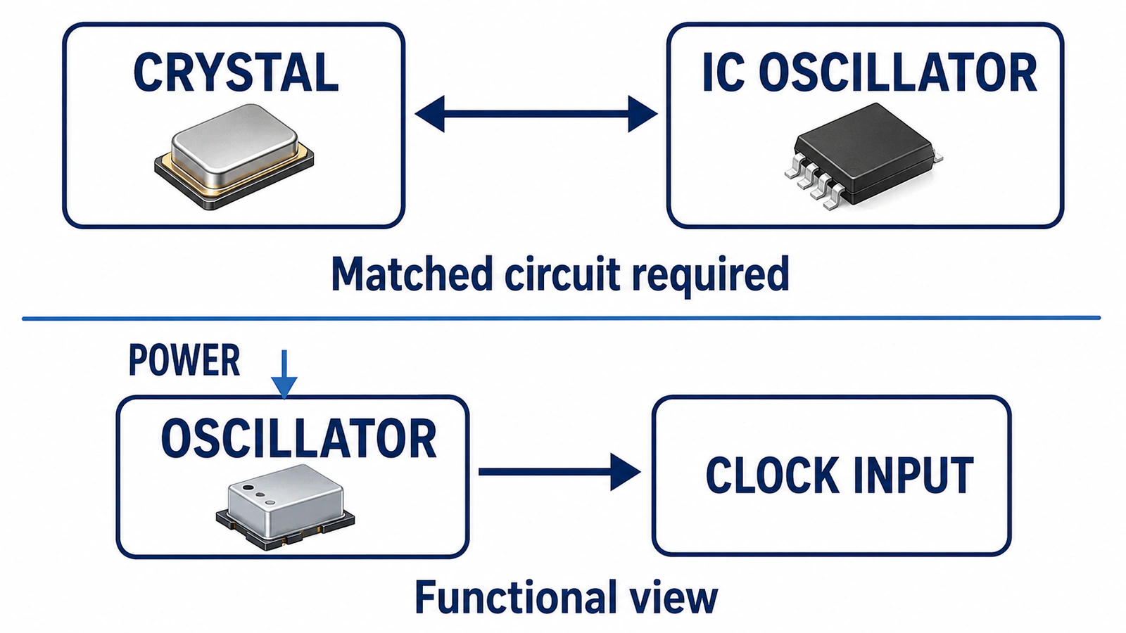 Conceptual comparison: a passive crystal needs a matched sustaining circuit; a powered oscillator supplies a clock to a compatible input.
Identify the function from the schematic and datasheets. A metal lid or four pads does not prove that a component is an oscillator.
For a passive device, use NTCHIP's Crystals category to find candidates after defining the circuit requirements.
When do XO, TCXO, VCXO, and OCXO matter?
Temperature compensation and voltage control describe different functions; some products combine them. For an OCXO, include the usable-clock requirement after power-on. NDK's OCXO guidance explains the thermal and warm-up considerations.
Define frequency and the complete ppm budget
Select a frequency supported by the receiving IC and its configured clock path. For a crystal, also preserve the specified resonance condition and fundamental or overtone mode. A frequency label alone does not describe how the circuit must operate.
Frequency tolerance is the initial deviation measured under stated reference conditions. Temperature stability describes variation across a specified temperature range. Aging describes change over a stated interval. ECS explains tolerance and stability, and Renesas includes aging in the crystal frequency budget.
Read the footnotes before adding limits. A combined or “overall” stability rating may already include some terms. Add separately specified worst-case allowances only when they are not already included; do not assume errors will cancel.
For a hypothetical 16 MHz design:
Convert ppm to hertz with:
Frequency error in Hz = nominal frequency in Hz × ppm / 1,000,000
Here, 16,000,000 × 30 / 1,000,000 = 480 Hz. The subtotal therefore corresponds to ±480 Hz. These values are illustrative, not a named component's specifications.
Engineering must allocate any remaining error from loading, supply sensitivity, calibration, or other relevant effects. Record the operating conditions and time interval alongside the limit. A first-year aging figure does not establish drift across the product's entire service life.
Match load capacitance to the oscillator circuit
A crystal's specified load capacitance, CL, is the external load at which its frequency is specified. It is not automatically the value of either capacitor connected to ground. The receiving IC, PCB, and external components together determine the effective load.
For a simplified network with two equal external capacitors, each of value C:
CL ? C / 2 + Cstray
Cstray represents the effective residual capacitance in this model. Microchip's oscillator-selection documentation gives this equal-capacitor relationship.
Suppose CL is 12.5 pF and engineering estimates an effective Cstray of 2 pF:
C ? 2 × (12.5 ? 2) = 21 pF per capacitor
This is a starting calculation for the stated model. The final capacitor values depend on the IC, layout, tolerances, and board measurements. Use the IC vendor's treatment of pin and board capacitance, and count each contribution once. An IC with internal or programmable loading may need a different external network.
Also distinguish CL from the crystal's shunt capacitance, C0. C0 is a separate equivalent-circuit parameter. Some receiving ICs specify a limit for it, as shown in Microchip's crystal design considerations.
For procurement, a different CL value is a technical change even when the frequency and footprint match. Ask engineering to assess the alternate and its load network together. If the circuit uses ceramic capacitors for loading, include their approved values, tolerances, and packages in the purchasing specification.
Check ESR, startup margin, and drive level together
ESR describes loss in the crystal's equivalent circuit. Compare its maximum specified value with the receiving IC's oscillator capability at the intended frequency and loading. A typical ESR value does not replace the maximum value needed for screening.
Startup also depends on the complete circuit. TI's AN100 selection guide evaluates negative resistance and startup margin for its RF devices. Use the margin requirement and measurement method applicable to the chosen IC. A ratio quoted for another device is not a universal acceptance rule.
Drive level is the power dissipated in the crystal. Its specified operating and maximum limits are different from the oscillator circuit's supply voltage or total supply current.
ST's AN2867 design guide explains drive measurement and the effect of a series resistor. Reducing drive can alter startup behavior, so evaluate both after changing the crystal, loading, or drive configuration.
Keep the following in the engineering comparison record:
Crystal maximum ESR and its specified conditions.
Permitted drive level and any recommended operating conditions.
Required startup time and startup-margin method.
Receiving IC configuration and board revision used for validation.
A room-temperature startup test documents one operating condition. Before production approval, complete the checks required across the design's intended supply and temperature conditions.
Treat 32.768 kHz crystals as a separate selection
A 32.768 kHz watch crystal must suit the receiving real-time clock (RTC) or low-frequency oscillator. Check that circuit's loading, ESR limit, drive capability, and startup requirements instead of carrying values over from a MHz crystal design.
Read units carefully: kΩ and Ω differ by a factor of 1,000, as do μW and mW. Epson's FC-135 datasheet illustrates why drive level, frequency conditions, and package details belong to a specific crystal selection. It is a reference example, not a recommended substitute.
For timekeeping, ppm can also be expressed as accumulated time error. If a clock maintained a constant 20 ppm error for 24 hours, the difference would be 86,400 × 20 / 1,000,000 = 1.728 seconds. Actual time error depends on temperature, aging, calibration, and other conditions; room-temperature tolerance alone does not establish daily performance.
For active oscillators, check the output and jitter
A powered oscillator must satisfy both its supply requirements and the receiving clock input's electrical limits. Preserve the output format and voltage option in the full ordering code.
Check output high/low levels, load, rise/fall times, and duty cycle where specified. Differential interfaces also require the correct connection, coupling, and termination. Epson's timing glossary distinguishes output loading and waveform parameters. An oscillator's capacitive output-load rating is different from a passive crystal's resonant CL.
Read the enable or standby function carefully. Record the disabled output state and the time until a usable clock is available after startup or re-enabling. These details can affect the receiver's reset sequence.
Compare the same jitter measurement
PPM describes frequency deviation; jitter describes timing variation. A tighter ppm specification does not prove that an oscillator meets a jitter requirement.
For RMS phase jitter, compare values at the relevant carrier frequency and integration band. For phase noise, compare the required offset frequencies. Analog Devices' MT-008 tutorial explains how integrating phase noise relates to time jitter.
Use the receiving system's clock requirement to shortlist parts in NTCHIP's Oscillators category. Keep active-oscillator candidates separate from passive crystals in the comparison.
Compare the mechanical drawing with the actual PCB footprint. Body dimensions, height, pad geometry, pin-one orientation, and pad functions all need to agree. A size label such as “3225” does not establish electrical interchangeability.
Follow the datasheet for grounding or leaving unused pads unconnected. Record the operating temperature at the component and any assembly, storage, shock, or vibration requirements relevant to the design.
For crystal circuits, short routing and the IC vendor's grounding guidance help control unwanted capacitance and noise coupling. Measurement can also load the circuit. ST's AN2867 guidance should be read alongside the selected IC documentation when planning layout and probing.
Before releasing an alternate, define acceptance checks for startup, frequency error, crystal drive, or oscillator output timing as applicable. Test the relevant supply and temperature conditions, then record the board revision, component ordering code, and result.
Package and option codes can hide purchasing differences. Epson's product configuration guide shows how frequency, loading, and other options enter ordering descriptions. Confirm the exact configuration with its manufacturer documentation; a shortened distributor title is insufficient.
Example: compare three crystals with the same frequency
Assume engineering specifies a passive 16 MHz crystal with 12.5 pF CL and a maximum permitted crystal ESR of 60 Ω. These are hypothetical screening requirements, not specifications for a named IC.
Candidate A passes only the two electrical screens shown. Its tolerance, temperature behavior, aging, drive limits, resonance mode, pad functions, and startup performance still need review.
Candidate B may work in a suitably designed circuit, but purchasing cannot treat it as an unchanged substitution. Candidate C exceeds the assumed limit even though its frequency and CL match.
Use a documented equivalent-part review to record why each candidate was retained or rejected. The next buyer can then review a revised quote or ordering suffix against the same criteria.
Prepare the specification before requesting parts
For an approved design, send the manufacturer and complete ordering code. For a new design or alternate search, attach a controlled requirement table and identify who must approve candidates.
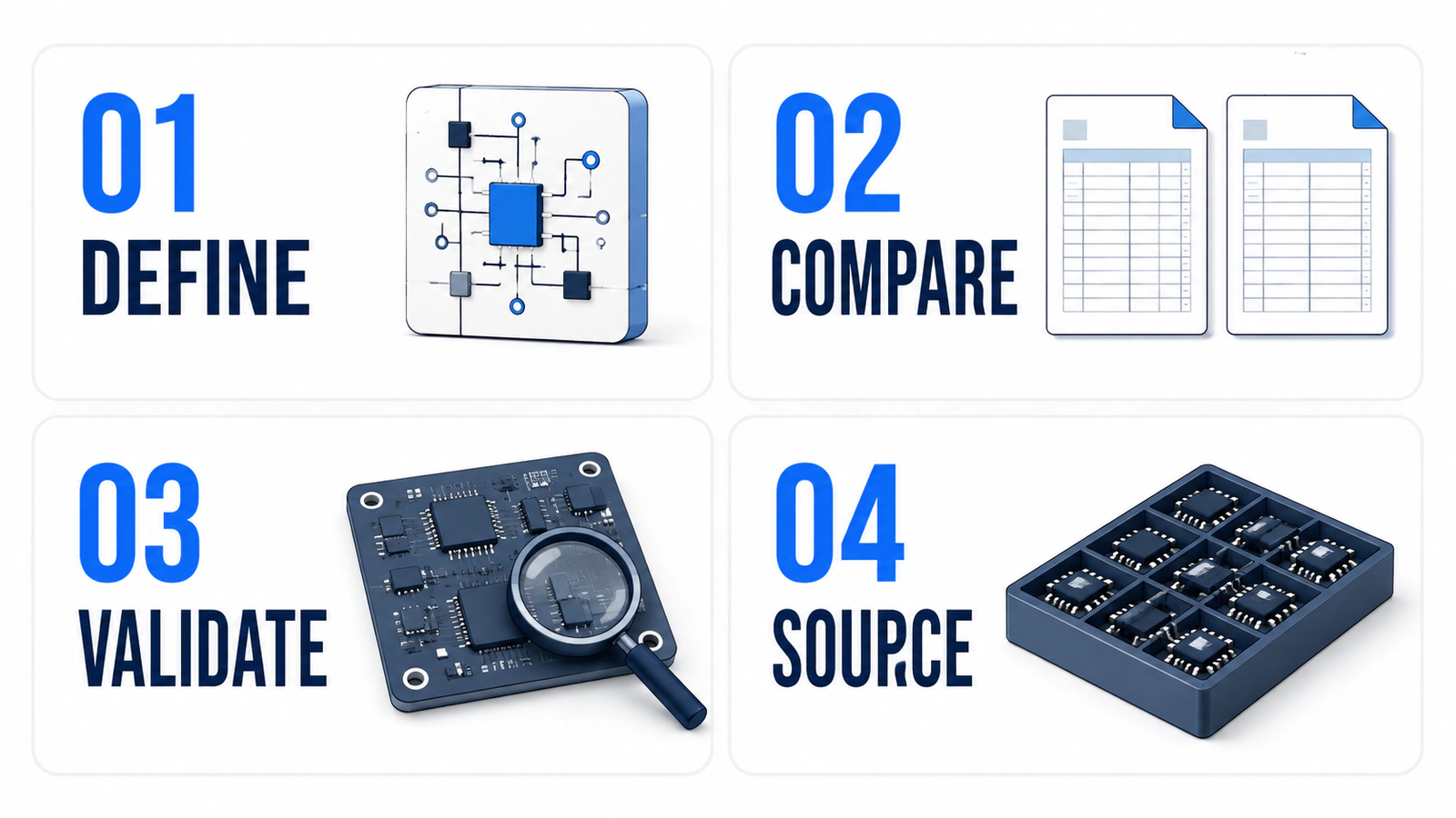 Define the circuit requirement, verify candidate datasheets and board performance, then source the documented configuration.
Confirm component lifecycle status using current manufacturer information. For older or constrained parts, agree on date-code or lot requirements, packaging condition, and available documentation before ordering. A photograph or matching label cannot demonstrate timing performance.
Use NTCHIP's quality-control information to discuss the checks and documents the order requires. Confirm the actual scope for that order; do not assume every component receives every listed inspection.
Then request a quote from NTCHIP with the exact part number or candidate specification. Availability, pricing, and lead time should be confirmed through RFQ.
Crystal oscillator selection FAQ
Can a crystal and an oscillator replace each other?
They require different circuit arrangements. A passive crystal works with a sustaining circuit; an active oscillator supplies a powered clock output. A change between them requires review of the schematic, the receiving IC's supported modes, and its electrical limits.
Does a 12.5 pF crystal need two 12.5 pF capacitors?
No. In a simplified equal-capacitor network, the two external capacitors contribute half of either value to the effective load, before residual capacitance is included. Use the receiving IC's model and verify the assembled board.
Is a lower ppm value always better?
Compare the same error terms and conditions. Lower initial tolerance does not necessarily mean lower total error across temperature and aging. Choose a part that meets the complete timing requirement and circuit constraints.
Can I replace a crystal with another of the same frequency and package?
Frequency and package are only initial checks. CL, ESR, drive limits, resonance mode, pad functions, and operating conditions can differ. Follow the design's datasheet comparison and board-validation requirements before approving an alternate.
Does a TCXO automatically have lower jitter?
No. Temperature compensation addresses frequency change with temperature. Jitter needs its own specification and comparison under matching measurement conditions.
Browse crystals with a defined requirement
Build the shortlist from the receiving circuit's requirements, then compare complete ordering codes and supporting documents. Keep engineering approval attached to any alternate.
Browse NTCHIP's Crystals category with frequency, CL, maximum ESR, drive limits, package, and quantity in hand. Include those requirements when asking the sourcing team to review a candidate.