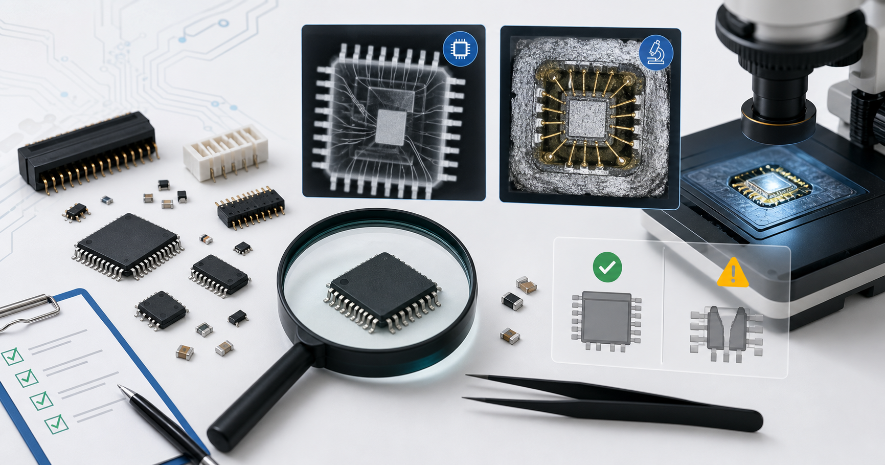
X-Ray inspection helps buyers and quality teams see internal features that are hidden by an electronic component package or by a soldered assembly. For electronic components, it is most useful for checking internal construction, wire bonding, die attach condition, voiding, cracks, delamination indicators, package anomalies, BGA solder joints, and lead-frame related issues.
It is not a single proof of authenticity or long-term reliability. X-Ray inspection should sit inside a wider quality-control process that may include visual inspection, documentation review, electrical testing, decapsulation, XRF or material analysis, acoustic microscopy, solderability checks, and application-specific review.
For high-risk, obsolete, or hard-to-find components, NTCHIP can help buyers discuss quality-control requirements before purchase. Buyers can review NTCHIP's Quality Control Process and confirm inspection needs through RFQ before placing an order.
Quick Answer: What Can X-Ray Inspection Detect?
X-Ray inspection can detect differences or anomalies in hidden internal structure. In electronic components and assemblies, common targets include die position, die attach voids, wire bond pattern, broken or missing wires, lead-frame structure, internal cracks, delamination indicators, package contamination, BGA solder joint shape, solder voiding, insufficient solder, head-in-pillow indicators, and other hidden assembly issues.
The practical question is not only "Can X-Ray see it?" It is "What decision will the image support?" A buyer may use X-Ray results to decide whether to continue inspection, reject a suspect lot, compare a sample against an exemplar, or request additional testing.
| Inspection question | X-Ray can help detect | X-Ray cannot confirm alone | Common paired methods |
|---|
| Is the internal construction consistent? | Die size/location, lead frame, bond wire layout, internal package structure | Manufacturer authorization or full authenticity | Documentation review, traceability review, decapsulation, comparison with known-good sample |
| Are there visible internal defects? | Cracks, broken wires, die attach voids, shifted die, package anomalies | Electrical performance under all operating conditions | Electrical testing, functional test, datasheet review |
| Are BGA or hidden solder joints acceptable? | Voids, bridging, opens, solder-ball shape, head-in-pillow indicators | Mechanical strength or long-term field reliability | AOI, process records, cross-section when justified, reliability qualification |
| Is the material composition correct? | Some density or structural differences | Alloy, plating, mold compound, or elemental composition | XRF, FTIR, SEM/EDS, laboratory material analysis |
| Is the part safe for a critical application? | Anomaly screening evidence | Application suitability or life expectancy | Engineering review, datasheet verification, customer-approved test plan |
What X-Ray Inspection Can Detect in Electronic Components
X-Ray inspection works because different internal materials absorb radiation differently. Metal features such as lead frames, bond wires, solder balls, and die attach regions usually appear with stronger contrast than mold compound or air gaps. The result is a non-destructive view of hidden structure.
Internal structure and package consistency
X-Ray can show whether the internal construction of a component is consistent across a lot or consistent with a known-good exemplar. Quality teams often review die size, die placement, lead-frame geometry, package cavity, and internal layout.
This is useful for high-risk sourcing because obvious internal differences may point to mixed lots, incorrect package construction, prior rework, or suspect parts. It does not prove that a part came from the original manufacturer.
Wire bonding issues
For many IC packages, X-Ray can reveal the bond wire pattern. Inspectors may look for missing wires, broken wires, shifted wires, abnormal loop shape, wire sweep, shorted wires, or inconsistent bonding compared with a reference sample.
Wire bonding review is especially useful when a part has a clear expected internal layout. If no exemplar is available, the inspection team may compare units within the same homogeneous sample population and review available technical data.
Die attach voids and die position
X-Ray can reveal voids in the die attach area, shifted die placement, tilted die indicators, or large attach anomalies. For power devices, modules, and thermally sensitive components, voiding may matter because the die attach path can affect heat transfer and mechanical integrity.
X-Ray images should be interpreted against the component type, application risk, and customer requirements. A void visible on an image is an inspection finding; the acceptance limit usually needs an agreed criterion or engineering review.
Cracks, delamination indicators, and internal damage
X-Ray can show certain cracks, delamination indicators, and internal damage when the geometry and contrast make them visible. It may also reveal damage caused by improper component removal from an assembly, excessive heat exposure, or mechanical stress.
Some delamination and package integrity issues are better evaluated with acoustic microscopy or destructive analysis. X-Ray is useful, but it should not be treated as the only package-integrity method.
Package anomalies and foreign material
X-Ray can help detect abnormal cavities, unexpected metal fragments, missing internal elements, inconsistent lead-frame trimming, abnormal package density, or foreign material with enough contrast. These findings can support lot screening and further investigation.
The method is strongest when the inspector has a known-good reference, customer requirement, or comparative lot sample.
BGA solder joints and hidden assembly defects
For assembled boards, X-Ray is widely used because BGA, QFN, bottom-terminated, and other hidden solder joints cannot be fully evaluated by normal visual inspection. It can detect solder voiding, bridging, insufficient solder, opens, ball collapse issues, head-in-pillow indicators, and abnormal solder joint shape.
IPC materials note that X-Ray can support inspection where solder conditions are not visible by other means, and BGA defect review often depends on X-Ray or CT methods. For acceptance, buyers should refer to the applicable assembly standard, customer requirement, or process agreement.
Lead-frame and terminal issues
X-Ray can reveal lead-frame deformation, missing or shifted internal leads, bent internal structures, poor alignment, and some package-to-lead anomalies. For components with hidden lead-frame construction, this can help detect damage that visual inspection would miss.
Lead-frame findings should be paired with external visual inspection and electrical testing when the application risk is high.
What X-Ray Cannot Confirm by Itself
X-Ray inspection is a strong non-destructive screening method, but it is not a universal quality verdict. It can reveal structure and anomalies; it cannot answer every sourcing, electrical, material, or authorization question.
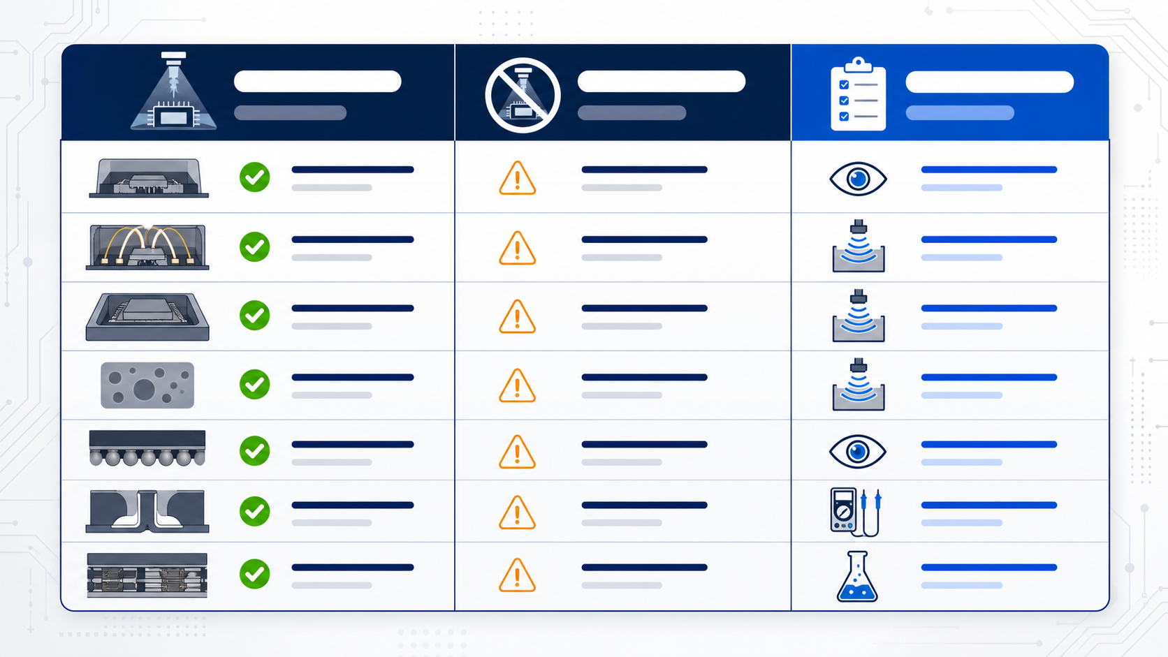
| Area | What X-Ray can show | What it cannot confirm alone | Better paired check |
|---|
| Counterfeit risk | Internal mismatch, missing die, abnormal wire bonds, reused package indicators | Complete authenticity or legal origin | Traceability review, supplier risk review, documentation check, decapsulation, electrical test |
| Electrical performance | Physical damage that may explain failure | Parametric performance, timing, leakage, gain, memory function, load behavior | Electrical or functional testing against datasheet requirements |
| Material composition | Density differences or unexpected internal structure | Elemental composition of leads, plating, mold compound, or die material | XRF, SEM/EDS, FTIR, material analysis |
| Manufacturer authorization | Nothing definitive | Authorized distributor status or manufacturer approval | Direct manufacturer/authorized-channel verification |
| Long-term reliability | Some structural risks such as voids or cracks | Field life, thermal cycling endurance, moisture sensitivity outcome | Reliability qualification, process history, datasheet and application review |
| Compliance and certification | No direct proof | RoHS, REACH, UL, automotive grade, aerospace grade, or customer certification | Supplier documentation and approved lab reports when required |
SAE AS6171 and SAE AS6171/5 are useful references for suspect counterfeit EEE parts because they frame radiological inspection as one method within a risk-based inspection and test process. AS6171 also makes an important point for buyers: testing can identify anomalies and risk indicators, but an unbroken chain of custody is the stronger basis for authenticity confidence.
For NTCHIP sourcing discussions, this means quality requirements should be stated before purchase. The RFQ should identify the component, quantity, application risk, documentation needs, and any requested inspection methods. Availability, pricing, lead time, and inspection scope should be confirmed through RFQ.
How to Use X-Ray Inspection in a Component Quality-Control Flow
X-Ray inspection works best when it answers a defined quality question. A clear process helps procurement, engineering, and quality teams avoid vague results.
1. Define the sourcing risk
Start with the risk profile of the component. Is it obsolete, shortage-driven, high value, safety related, moisture sensitive, thermally stressed, or used in a high-cost assembly? Is the chain of custody complete or limited?
The higher the risk, the more important it is to define inspection requirements before purchase.
2. Confirm the exact component identity
Before reviewing an X-Ray image, confirm the manufacturer name, full part number, package, date code requirement, quantity, lifecycle status, and datasheet. If the part is a replacement candidate, compare electrical ratings, package, pinout, thermal profile, and application requirements.
NTCHIP's product sourcing page can support broad component searches, but exact part and quality requirements should still be confirmed through RFQ.
3. Choose a sample plan and acceptance basis
Decide whether the inspection is for sample screening, lot comparison, failure analysis support, or incoming quality control. Define whether the acceptance basis is a customer specification, known-good sample, applicable standard, or engineering judgment.
Without this step, an X-Ray image may show an anomaly without telling the buyer what to do next.
4. Compare images against a useful reference
When possible, compare the sample with a known-good part or a trusted exemplar. If no exemplar is available, compare units within the same lot and review available technical data. Look for differences in die size, bond wire count, wire routing, lead-frame shape, die attach, and package construction.
5. Pair X-Ray with the right follow-up tests
If X-Ray shows an anomaly, the next step depends on the risk. A BGA void may require assembly-process review. A missing wire may require rejection or destructive confirmation. A material concern may require XRF or SEM/EDS. A performance concern requires electrical testing.
X-Ray should guide the next decision, not replace the full decision.
X-Ray Inspection Checklist for Quality Engineers and Technical Buyers
Use this checklist before requesting X-Ray inspection for electronic components.
RFQ and lot information
Full manufacturer name and exact part number
Package type, quantity, and target delivery date
Date code, lot code, and packaging requirements if applicable
Application risk level and whether the part is used in a critical assembly
Known chain-of-custody or traceability documents, if available
Whether the component is obsolete, EOL, shortage-driven, or sourced outside the authorized channel
X-Ray inspection scope
Required sample quantity or lot sampling plan
Inspection target: internal structure, wire bonds, die attach, voids, cracks, BGA joints, or lead frame
Reference basis: known-good exemplar, same-lot comparison, datasheet information, customer criterion, or agreed risk screen
Required image views, magnification, and reporting format
Whether 2D X-Ray is enough or CT review may be needed
Image review points
Die size, die placement, and die tilt indicators
Wire bond count, routing, loop shape, missing wires, broken wires, or wire sweep
Die attach coverage and void pattern
Cracks, delamination indicators, abnormal cavities, or foreign material
Lead-frame geometry and terminal alignment
BGA solder-ball shape, bridging, opens, voiding, head-in-pillow indicators, or insufficient solder
Follow-up decisions
Accept, reject, hold, or escalate the lot based on the agreed criterion
Request electrical testing when performance risk remains
Request material analysis when composition risk remains
Request documentation review when traceability or authorization risk remains
Record findings and retain images for purchasing and quality records
For sourcing support, buyers can send a BOM or exact part list through NTCHIP RFQ and include any quality-control requirements in the inquiry.
When Should Buyers Request X-Ray Inspection?
Buyers should consider X-Ray inspection when the cost of a hidden defect is higher than the cost of screening. It is especially useful when ordinary visual inspection cannot see the risk.
Good use cases include:
Obsolete or hard-to-find ICs with limited traceability
High-value semiconductors, power modules, or industrial components
BGA, QFN, LGA, CSP, and bottom-terminated assemblies
Components recovered from assemblies or suspected of prior rework
Lots with mixed date codes, inconsistent marking, or unclear documentation
Parts for equipment where failure could create high repair, downtime, or safety cost
Incoming quality checks where the customer requires X-Ray evidence
X-Ray may be unnecessary for low-risk commodity components from a trusted, traceable source. It may also be insufficient for risks that are mostly electrical, chemical, or documentation based.
NTCHIP can help buyers discuss inspection expectations for high-risk components, but inspection scope, acceptance criteria, availability, pricing, and lead time should be confirmed through RFQ.
FAQ
Can X-Ray inspection prove an electronic component is authentic?
No. X-Ray inspection can identify anomalies that may indicate counterfeit risk, such as inconsistent internal construction, missing die, abnormal wire bonds, or reused-package indicators. It cannot prove manufacturer authorization or complete authenticity by itself.
Can X-Ray inspection detect broken wire bonds?
Often, yes. X-Ray can show missing, broken, shifted, or shorted bond wires when image resolution and package geometry allow it. The finding should be compared with a reference sample or technical data when available.
Can X-Ray detect die attach voids?
Yes. Die attach voids are one of the common reasons to use X-Ray inspection. The acceptance decision depends on component type, thermal requirements, application risk, and the agreed criterion.
Can X-Ray inspect BGA solder joints?
Yes. BGA solder joints are hidden under the package, so X-Ray is commonly used to detect voids, bridges, opens, abnormal ball shape, insufficient solder, and possible head-in-pillow indicators.
Can X-Ray detect delamination?
Sometimes. X-Ray may show delamination indicators or related package anomalies, but acoustic microscopy is often more suitable for detailed delamination analysis.
Does X-Ray inspection replace electrical testing?
No. X-Ray shows physical structure. Electrical testing is needed when buyers must confirm parametric or functional performance against a datasheet or customer requirement.
Should every sourced component receive X-Ray inspection?
No. X-Ray should be risk based. It is more useful for high-risk, high-value, obsolete, hidden-joint, or quality-sensitive components than for low-risk parts from traceable channels.
Conclusion: Use X-Ray as a Risk Screen, Not a Standalone Verdict
X-Ray inspection gives quality teams a practical way to inspect hidden structures in electronic components. It can detect internal construction differences, wire bonding problems, die attach voids, cracks, package anomalies, lead-frame issues, and hidden solder-joint defects such as BGA voids or bridges.
Its value increases when the inspection has a clear question, a reference basis, and a defined follow-up path. For counterfeit risk, electrical performance, material composition, manufacturer authorization, and long-term reliability, buyers should pair X-Ray with the right documentation, test, and engineering review.
View NTCHIP Quality Control Process
If you are sourcing high-risk, obsolete, or quality-sensitive components, review NTCHIP's Quality Control Process. To discuss a specific part, send the full manufacturer part number, quantity, target date, and inspection requirements through NTCHIP RFQ.