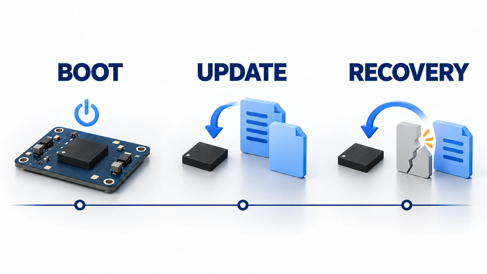
A replacement SPI NOR flash can pass the programmer's verify step and still fail in the product. Verify proves that the bytes reached the array. It does not prove that the boot ROM can read them after a warm reset, that the update tool erases only what it should, or that the board recovers when power drops in the middle of an erase. Most teams reach this point because the original part is going end-of-life or has become hard to buy. This guide sets out an SPI NOR flash replacement plan in three stages: boot, firmware update, and recovery. Where a behavior is documented only for specific devices or software, we name the source and its conditions so you can check whether it applies to your design.
Define the Replacement and Freeze the Test Baseline
Before testing, write down exactly which part replaces which, and exactly which system the results will apply to.
Compare the complete ordering codes
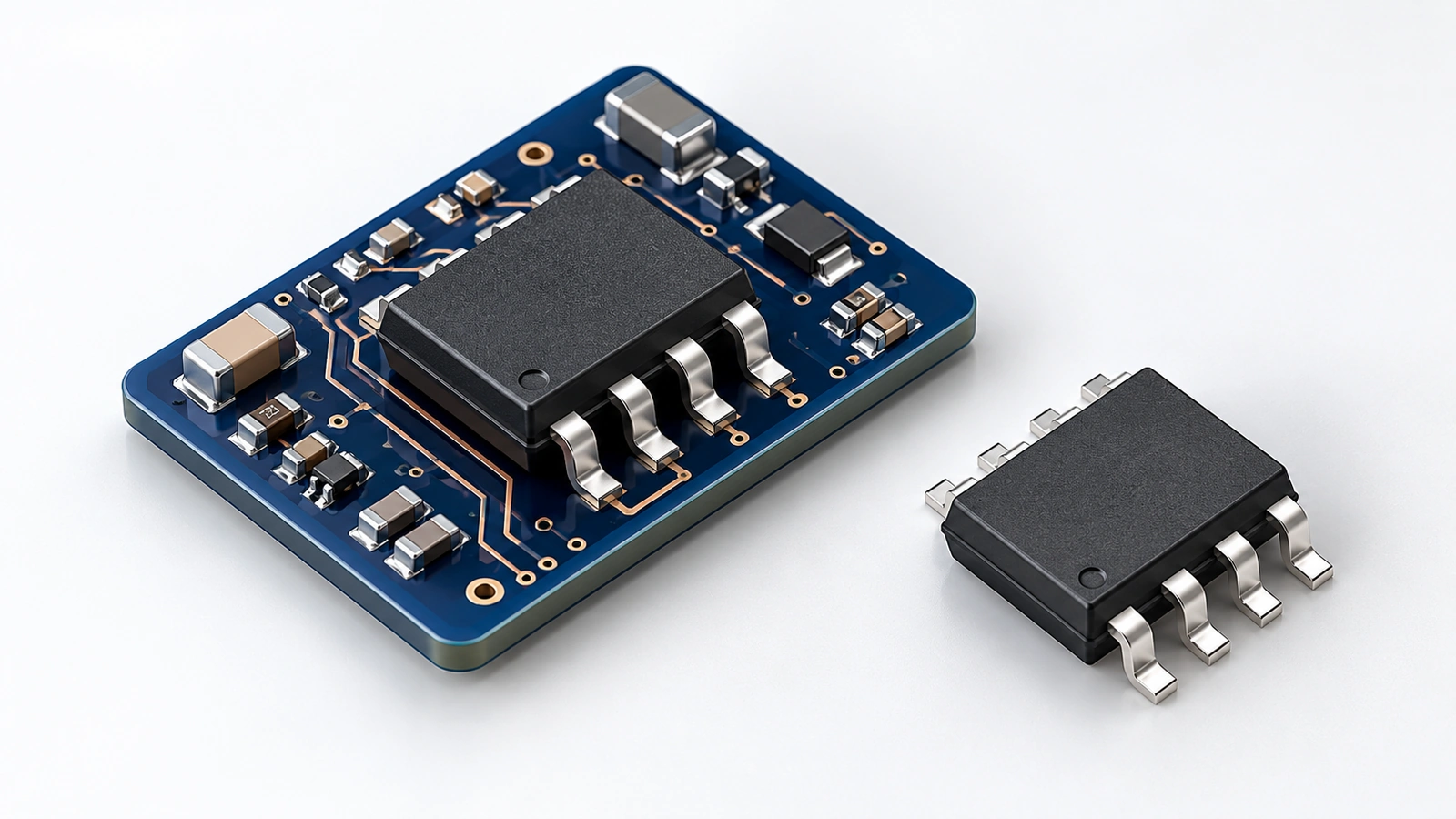
Compare full orderable part numbers, not family names. Suffixes can change the package, temperature grade, supply range, default I/O mode, and whether a reset pin is bonded out. Then compare the package drawing and pinout, VCC and I/O voltage, capacity, erase sizes, endurance and retention, and the status and configuration registers. Register maps differ between vendors more than headline specifications do, and drivers depend on them. If you are still screening candidates, start with our guide to finding an electronic component equivalent safely.
A larger candidate needs extra attention. Three-byte addressing reaches 16 MB (128 Mbit); beyond that, the device needs four-byte addressing, through four-byte commands or a mode switch, and that choice affects how the flash behaves after a reset. Decide whether the extra capacity will be used, and check that the bootloader, driver, and partition table all agree on the size.
Record the board, firmware and flash map
Record the board revision, the boot chain (boot ROM settings, bootloader, kernel or RTOS), the flash driver and its version, the update tool, the image checksums, and the flash map with every partition's offset and size.
Generic driver support helps but has limits. The Linux kernel can often probe a flash that publishes SFDP parameter tables without a device-specific entry, but its SPI NOR documentation notes that settings SFDP does not cover, such as block protection, and incorrect SFDP data still need specific handling. Support in one upstream kernel does not show that the software you ship, or the boot ROM, supports the candidate.
| Item | Original part / current system | Candidate / change | Risk to validate |
|---|
| Full ordering code | Original code and datasheet revision | Candidate code and datasheet revision | Suffix differences: package, grade, reset pin |
| Package and pinout | Drawing reference | Drawing reference | Footprint fit; RESET#, HOLD#, and WP# functions |
| Supply and I/O voltage | Operating range | Operating range | Margin near brown-out thresholds |
| Capacity and addressing | Size; 3- or 4-byte | Size; 3- or 4-byte | Address mode after reset |
| Erase and program sizes | Sector and block sizes | Sector and block sizes | Update alignment; adjacent data |
| Registers and protection | Register map | Register map | Driver writes, protection bits, quad enable |
| Software in the boot path | Boot ROM settings, bootloader, driver versions | Changes required | Support in shipped software, not only upstream |
| Images and flash map | Checksums; partition table | Changes | Partition boundaries; reserved areas |
Validate Boot Across Power and Reset Conditions
Test boot from every state the flash can be in when the processor starts reading, not only from a fresh power-up. A programmer verify and one successful cold boot cover the easiest of those states.
Cold start and the first flash access
At power-on, the boot ROM or first-stage loader reads the flash with fixed settings: a command, an address length, a clock rate, and often a configuration header stored in the flash itself. Capture that first access on CS#, SCK, and the data lines, and confirm that the candidate answers it as the original did.
Check whether your platform keeps flash settings in the image. On NXP's i.MX RT595, for example, when flash auto-probe is not enabled in the fuses, the boot ROM reads a flash configuration block at offset 0x400 and uses it to set up the FlexSPI interface (AN13304). That block was written for the original device. If the candidate needs different read commands, dummy cycles, or clock settings, the image can program and verify correctly and still not boot until the block is updated.
Warm reset after normal operation
A warm reset restarts the processor but not necessarily the flash. Whatever state the application left the flash in, such as an address mode, a quad mode, or a register setting, may still be active when the boot ROM issues its first read.
The four-byte address case is well documented. Macronix's AN053 describes the MX25L25635E staying in 32-bit address mode through a system reset that does not power-cycle it, so a boot read with 24-bit addresses fails. It recommends the hardware RESET# pin, an exit-four-byte-mode command issued first in the reset sequence, or a power cycle. Infineon reports the same symptom for the S25FL256S and recommends a version with a reset input; on that family, RESET# is not available in every package.
To test it, run the application until it has used the flash the way it does in the field, then trigger each reset source the product has: software reset, watchdog, and external reset or supervisor. On the candidate's board wiring, confirm whether the reset actually reaches the flash.
Brown-out and rapid power cycling
A supply that dips without falling far enough, or returns too quickly, can leave the flash without a clean power-on reset. Infineon's brown-out guidance for its SPI flash families states that once VCC falls below the cut-off level, it must stay below VCC(LOW) for tPD before ramping up again, or the device may not initialize correctly. Fast off-on cycles are a common cause. The thresholds and times come from each datasheet, so compare them between the original and the candidate, and against how fast your supply actually discharges.
| Start state / supply condition | Trigger | Waveforms and logs | Pass criterion |
|---|
| Unpowered; nominal supply ramp | Power on | VCC ramp, CS#, SCK, first command; boot log | Boots every cycle; first access matches expected command, address length, and clock |
| Running; flash in its field state (address mode, quad mode, after writes) | Software reset | CS#, RESET# if present, first command; boot log | Boots; flash is in the mode the boot ROM expects |
| Running; same state | Watchdog reset | Same as above | Same as above |
| Running | External reset or supervisor | RESET# at the flash pin; first command | Reset reaches the flash, or the boot path tolerates its state |
| Running | Power off and on with short off-times | VCC at the flash against VCC(LOW) and tPD; boot log | Boots after every off-time tested, or a minimum off-time is documented |
| Running | Supply dip below operating range without full power-off | VCC trace, supervisor output; boot log | Clean reset, or the dip is shown not to occur in the product |
Testing more than one candidate?
Send the full ordering code and the sample quantity for each. NTCHIP has no minimum order quantity.
Validate the Complete Firmware Update Path
Test the update with the software and tools that will run in the field, on the real flash map, and check three things separately: the new image, the data next to it, and the update state the bootloader reads.
Exercise erase, program and readback at boundaries
Run erase, program, and readback in an area engineering has approved for destructive testing. Include the boundaries where devices differ: page boundaries, erase-block boundaries, the end of each partition, and the highest addresses, including the region above 16 MB on a larger candidate. Compare readback checksums with the source image.
Then erase again and read back. The kernel's minimum testing requirements for SPI NOR include this second erase because a new flash arrives erased, so a first erase that silently did nothing would go unnoticed. Those requirements were written for adding driver support. For a product, treat them as a floor.
Check the data next to each image, too. Update tools work in erase units, and erase sizes may differ between the original and the candidate. U-Boot's sf update, for instance, works one erase sector at a time and skips sectors that already hold the right data; when the length is not a multiple of the erase size, the space after the data in the last sector is erased. If settings, calibration data, or a second image share that sector, they are lost. Map every partition boundary against the candidate's erase sizes.
Check write protection as well. If the product uses block protection to guard the bootloader or settings, confirm that the update path unlocks only the region it writes and restores protection afterward, using the candidate's protection bits. Block protection is one of the settings the kernel documentation lists as outside SFDP, so generic support does not cover it.
Check activation, confirmation and rollback
An update is not complete when the bytes are written. The bootloader must activate the new image, the image must confirm itself, and an unconfirmed image must be rolled back.
In MCUboot, for example, a test swap boots the new image, and unless the image is confirmed, MCUboot performs a revert swap on the next boot; a permanent swap does not revert. Test the path your product uses: a confirmed update, an update that is never confirmed, and an image that fails verification. After each step, read the update state from the flash, not only from the application log.
| Stage / boundary | Operation and input | Data and state evidence | Pass criterion |
|---|
| Page and erase-block boundaries | Program across boundaries with the field update tool | Readback checksum | Matches source image |
| Second erase | Erase the tested range again | Readback | Fully erased |
| Partition ends and high addresses | Update an image that fills its partition; test above 16 MB on larger parts | Checksums of the image and the next partition | Image correct; next partition unchanged |
| Adjacent data | Update with a length that is not an erase-size multiple | Checksum of data after the image | Unchanged, or layout changed so no data shares the last sector |
| Write protection | Update with protection set as in the field | Protection register readback before and after | Only the target region unlocked; protection restored |
| Activation | Install a valid image | Update state in flash; boot log | New image boots |
| Confirmation | Confirm the new image | Update state after the next reboot | New image stays active |
| Rollback | Leave the image unconfirmed; separately, install an image that fails verification | Update state; boot log | Previous image restored; failed image not run |
Prove Recovery After Interrupted Operations
Decide in advance which states the product may recover to. Then interrupt each flash operation at defined points and prove that the product reaches one of those states and can still accept the next update.
Recovery testing finds failures that normal testing cannot: an update that works unless power fails at one particular moment. Define the acceptable outcomes first. For example, the previous image boots, the new image boots, or the device enters a defined recovery mode. A device that needs an external programmer to recover may be acceptable for one product and not for another. That is a product decision, not a test result.
Interrupt operations at defined checkpoints
Cut power, or assert reset, during each operation that changes the flash: during a sector erase, during page programming, after the new image is written but before activation, while the bootloader writes its swap or status metadata, and after activation but before confirmation. Drive a power switch from a test script and trigger the cut from a GPIO, a log line, or a measured delay, so each checkpoint is repeatable. Vary the timing within each operation.
A well-designed bootloader is built for this. MCUboot's design requires it to work when reset in the middle of an image swap, and it resumes an interrupted swap by reading the swap information in the image trailer. Actual recovery still depends on the upgrade mode and configuration you built, and on the flash behaving as the bootloader expects after a cut. That is why the test runs on the candidate.
Separate array recovery from register-write risk
Treat data in the memory array and settings in the registers as two different problems.
For the array, a correct-looking readback after an interruption proves nothing. Infineon's guidance on interrupted program and erase states that the interrupted location is indeterminate and may even show an apparently correct copy of the intended data. It recommends erasing an interrupted sector again, writing interrupted data to a new location instead of reprogramming the same one, and using start and end markers to identify which operation was cut short. Some devices also offer an erase-status command; check whether the candidate has one and whether your software uses it.
Registers are a separate risk. Status and configuration registers hold settings such as block protection, quad enable, and address mode, and datasheets classify those bits as volatile, nonvolatile, or one-time programmable. The split differs between vendors and families. Erasing an array sector does not repair an interrupted nonvolatile register write, and a one-time-programmable bit set in error cannot be cleared. Infineon publishes separate guidance on power loss during Write Register (WRR) operations. List every register write the shipped firmware can perform in the field. Either include each one as an interruption point or move it to production programming, where power is controlled.
Verify the recovery route on the target board
Run recovery on the production board with production firmware and the candidate fitted. Record whether each recovery was automatic or needed a service action, such as a recovery mode, a serial or USB loader, or an external programmer.

Define the acceptable end states.
Keep the baseline images and their checksums.
Inject the fault at the chosen checkpoint.
Restore power or release reset.
Read the boot and update logs.
Verify the running image and the data that must survive.
Install a further update to prove the device is not stuck.
| Interrupted operation | Checkpoint | Affected state or area | Expected recovery | Evidence and pass criterion |
|---|
| Sector erase | During erase | Sector being erased | Sector erased again before reuse; a valid image boots | Boot log; running image checksum; sector erase verified |
| Page program | During programming | Page being written | Data written to a new location, or the sector erased again | Image checksum; interrupted location not used |
| Image write complete | Before activation | New image slot | Previous image boots; update can be retried | Update state; boot log |
| Bootloader metadata write | During swap or status write | Trailer or status area | Swap resumes or reverts to a bootable image | Trailer state; running image checksum |
| New image active | Before confirmation | Update state | Revert as the configured mode defines | Boot log on the next boot |
| Register write (if done in the field) | During the write | Status and configuration registers | As the datasheet and product policy define | Register readback against expected values; boot after a power cycle |
Release a Qualified Configuration and Prepare the RFQ
Release the SPI NOR flash replacement for the exact configuration you tested, and give purchasing a request that carries that context.
Keep the approval tied to the tested configuration
A pass applies to the full ordering code, board revision, and software versions in the test. A different suffix, a new bootloader release, or a board change can reopen boot or recovery questions. The approval record should include:
Original and candidate full ordering codes, with datasheet revisions
Board revision and the change list (BOM, layout, firmware, boot configuration)
Software versions in the boot and update path, and the image checksums
Results of the boot, update, and recovery matrices, with logs and captures
Open issues, limits such as a minimum power-off time, and the approver
Keep supplier documents with this record. Our comparison of CoC, CoA, test reports, and traceability records explains what each one covers.
Send a sourcing request with engineering context
A request that names only the candidate invites a quote for the wrong suffix or the wrong quantity. Include these fields:
Original part number (full ordering code):
Candidate part number(s) (full ordering code):
Validation status: not started / samples for testing / approved for production
Approved alternates, if any:
Quantity: samples / pilot build / production (annual volume)
Target date:
Packaging: cut tape / reel / tray
Documentation needed: CoC / datasheet revision / date code limits
If other BOM lines need the same cleanup, see how to prepare a BOM for RFQ.
Send the original and candidate part numbers
Include the validation status and the fields above. We'll review each part and reply with what we can confirm, from validation samples to production volume. There is no minimum order quantity.
Availability, pricing, and lead time are subject to confirmation at the time of quotation.
Frequently Asked Questions
Can the original firmware stay unchanged?
Sometimes. If the software you ship identifies and drives the candidate correctly, the candidate behaves like the original after every reset the product uses, and the flash map does not change, the firmware may need no changes. Generic support such as SFDP probing helps but does not cover every setting, and device states such as four-byte address mode after a warm reset can still break boot. The validation results decide; the datasheet comparison only shows where to look.
How many power cycles should the test plan include?
There is no universal number. Set it from the product's environment and requirements: how unstable field power is, how many reset sources and interruption checkpoints there are, how widely timing is varied within each operation, and the reliability target. Run every checkpoint in the recovery matrix across a spread of interruption timings, repeat the rapid power cycles across the off-times your supply can produce, and record the counts and the reasoning with the approval.
Sources
Linux kernel documentation, SPI NOR framework
NXP, AN13304: Boot from QSPI Flash on MIMXRT595-EVK
Macronix, AN053: MX25L25635E 256Mb Serial Flash Application in System Reset
Infineon, S25FL256S boots from power-on but not from a warm reset
Infineon, S25FL128S/S25FL256S datasheet
Infineon, Power-down timing requirements and brown-out recovery for SPI flash
Infineon, Recover flash devices after power failure or reset during program or erase
Infineon, Power loss during the Write Register (WRR) operation in serial NOR flash
U-Boot documentation, sf command
MCUboot, Bootloader design